
DSTIKE 10 dBi Directional Wi-Fi Antenna - 2.4 GHz, U.FL/IPEX
$9.00
Skip to product information



DSTIKE 10 dBi Directional Wi-Fi Antenna - 2.4 GHz, U.FL/IPEX
DSTIKE 10dBi Directional Wi-Fi Antenna
$9.00
Translation missing: en.dstike.delivery.title
- Translation missing: en.dstike.delivery.standard
- Translation missing: en.dstike.delivery.express
Translation missing: en.dstike.delivery.estimate
Translation missing: en.dstike.delivery.dispatch
Translation missing: en.dstike.delivery.detailsFocused 2.4GHz Coverage for Compatible ESP32 and ESP8266 Projects
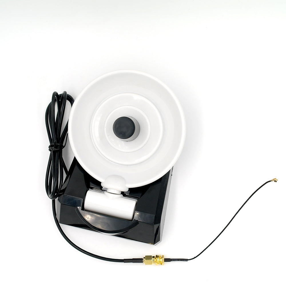
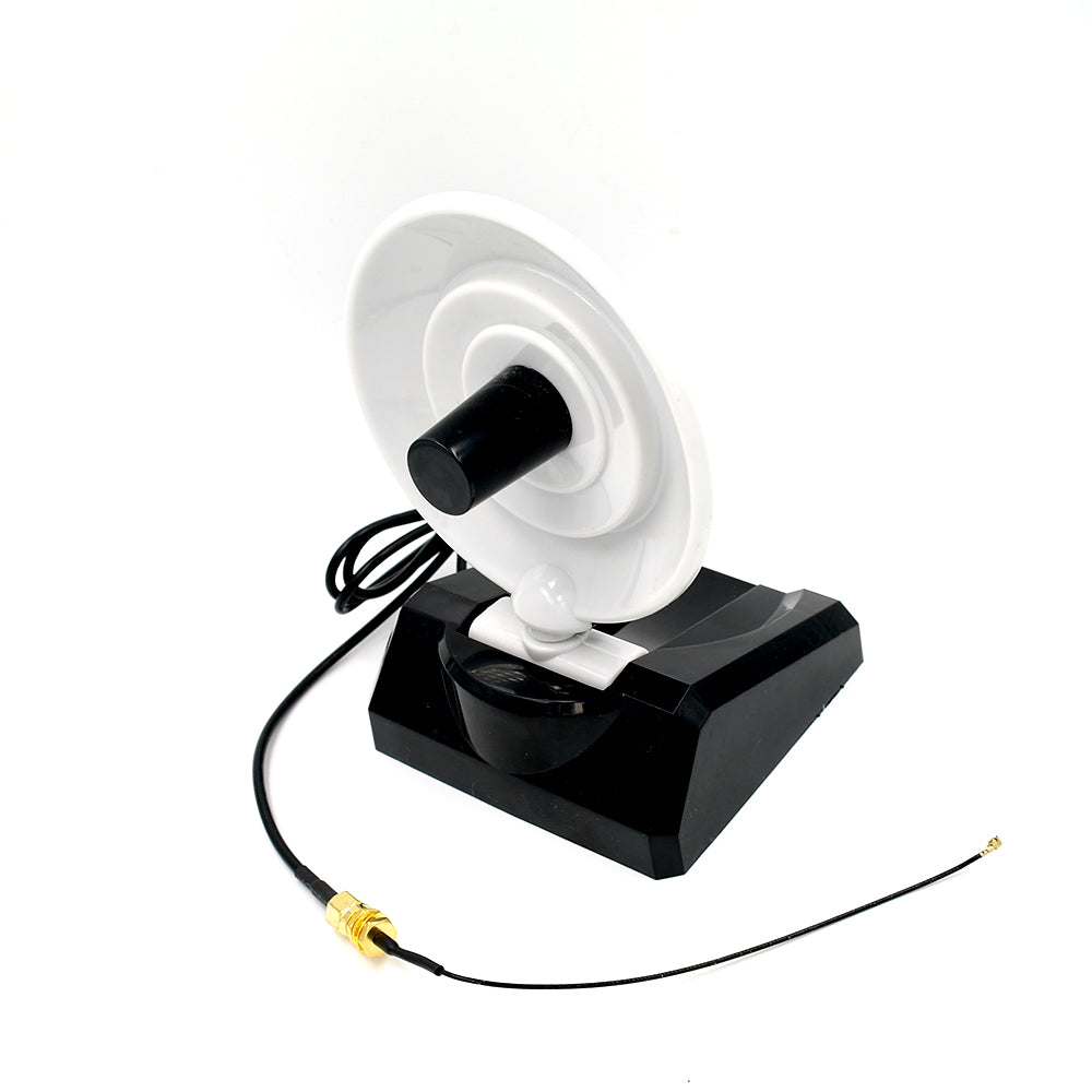
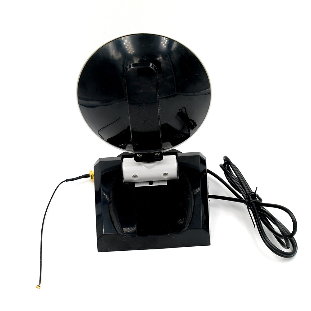
The DSTIKE 10dBi Directional Wi-Fi Antenna is a passive, high-gain antenna designed to concentrate 2.4GHz radio energy toward a specific direction.
Compared with an omnidirectional antenna, its focused radiation pattern can improve the link budget, signal reception, and connection stability between properly aligned compatible devices.
It is suitable for directional Wi-Fi links, ESP32 and ESP8266 development projects, wireless testing, point-to-point experiments, and other authorized 2.4GHz applications.
Important: This Is a Directional Antenna
A directional antenna does not provide equal 360-degree coverage.
It is designed to focus more of its available radio energy toward the direction in which it is aimed. This makes it useful when the remote access point or device is located in a known direction.
For the best results:
-
Aim the antenna toward the remote device
-
Adjust its direction slowly while monitoring RSSI or connection quality
-
Keep both ends of the link correctly oriented
-
Minimize walls, metal objects, and other obstructions
-
Use the shortest practical RF cable
-
Confirm that the connected device is configured for its external antenna port
Signal strength outside the main coverage direction may be lower than with an omnidirectional antenna.
10dBi Nominal Gain
The antenna provides a nominal gain of 10dBi within its specified 2.4GHz operating range.
Antenna gain does not increase the radio transmitter’s electrical output power. Instead, it concentrates the transmitted and received energy into a narrower directional pattern.
Actual improvement depends on:
-
Antenna alignment
-
Radio transmit power
-
Receiver sensitivity
-
Cable and connector losses
-
Access-point antenna design
-
Distance between devices
-
Buildings, walls, trees, and metal objects
-
Nearby 2.4GHz interference
-
Local regulatory power limits
A 10dBi rating does not guarantee a specific communication distance or internet speed.
2.4GHz Frequency Range
The antenna is designed for approximately:
2400–2500MHz
This frequency range covers common 2.4GHz applications such as:
-
2.4GHz Wi-Fi
-
ESP-NOW
-
Compatible Bluetooth and Bluetooth LE devices
-
Compatible 2.4GHz IoT projects
-
Wireless development and signal-monitoring equipment
Important Frequency Notice
This antenna is designed for 2.4GHz operation only.
It is not designed for:
-
5GHz Wi-Fi
-
6GHz Wi-Fi
-
Wi-Fi 6E
-
Sub-GHz systems
-
868MHz or 915MHz LoRa
-
GPS
-
4G or 5G cellular networks
Using the antenna outside its specified frequency range can result in poor performance and excessive signal reflection.
IPEX/U.FL-Style Connector
The antenna is supplied with a small IPEX/U.FL-style RF connector for compatible development boards and wireless modules.
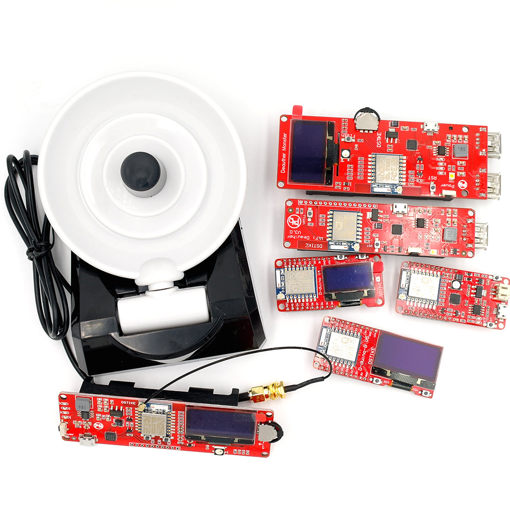
It is intended for boards that provide a matching external antenna socket, including selected versions of:
-
ESP-07 modules
-
ESP32-WROVER modules
-
ESP8266 development boards
-
ESP32 development boards
-
DSTIKE products with compatible IPEX sockets
-
Other 2.4GHz 50-ohm radio modules
Not every ESP-07, ESP32-WROVER, ESP32, or ESP8266 board includes an external antenna connector. Check the exact hardware version before ordering.
This antenna cannot connect directly to an SMA or RP-SMA socket without the correct adapter or pigtail.
External Antenna Selection
Some ESP32 and ESP8266 modules include both a PCB antenna and an external antenna connector.
Depending on the module, a resistor, jumper, RF switch, solder bridge, or firmware setting may be used to select the external antenna path.
Simply connecting an external antenna does not guarantee that the radio is using it.
Review the board schematic and manufacturer documentation before changing the antenna configuration. Incorrect modification of small RF components can permanently damage the board.
Technical Specifications
-
Product type: Directional 2.4GHz antenna
-
Nominal gain: 10dBi
-
Frequency range: 2400–2500MHz
-
Nominal impedance: 50 ohms
-
Nominal VSWR: ≤1.5
-
Connector: IPEX/U.FL-style micro RF connector
-
Approximate length: 195mm
-
Operation: Passive antenna
-
Intended use: Compatible 2.4GHz transmit and receive applications
Specifications are nominal. Actual performance can vary with installation, connected hardware, manufacturing tolerance, surroundings, and measurement method.
Directional vs. Omnidirectional Antennas
Choose this directional antenna if:
-
The remote device is in a known direction
-
You want to focus coverage toward a specific room or area
-
You are building an authorized point-to-point link
-
You can carefully align both ends of the connection
-
Reducing reception from other directions is desirable
Choose an omnidirectional antenna if:
-
Devices are located in multiple directions
-
You need general coverage around the antenna
-
The antenna orientation changes frequently
-
You cannot aim the antenna toward a fixed location
Higher gain is not automatically better. The correct radiation pattern is often more important than the numerical gain rating.
Recommended Applications
-
ESP32 and ESP8266 development projects
-
Authorized point-to-point Wi-Fi experiments
-
Directional signal-monitoring setups
-
Fixed-location IoT installations
-
Laboratory RF demonstrations
-
Wireless coverage experiments
-
Compatible 2.4GHz Bluetooth projects
-
DSTIKE devices with a matching external antenna connector
Installation Recommendations
-
Disconnect power from the radio device.
-
Confirm that the antenna connector matches the board socket.
-
Align the IPEX/U.FL connector directly above the socket.
-
Press it straight down using light, even pressure.
-
Do not force, twist, or repeatedly reconnect the miniature connector.
-
Confirm that the board is configured for its external antenna path.
-
Reconnect power and aim the antenna toward the intended device.
-
Adjust orientation while monitoring signal strength or connection quality.
Do not pull on the coaxial cable when disconnecting it. Lift the connector vertically with a suitable RF connector tool whenever possible.
Placement Recommendations
For better performance:
-
Keep the antenna away from large metal surfaces
-
Avoid placing it directly against batteries or shielded enclosures
-
Keep the RF cable away from high-current switching circuits
-
Do not sharply bend or crush the coaxial cable
-
Avoid unnecessary adapters and long extension cables
-
Mount the antenna securely after finding the best orientation
This product is not described as weatherproof. For outdoor installation, place it inside a suitable RF-transparent weather-resistant enclosure.
Regulatory Notice
A higher-gain antenna can increase effective radiated power in its main direction.
The combined transmitter power, antenna gain, and cable loss must comply with the radio regulations applicable in the country or region of operation. Some certified wireless products may only be approved for use with specific antenna types or maximum gain values.
The installer and user are responsible for confirming regulatory and equipment compatibility.
Package Contents
-
1 × DSTIKE 10dBi Directional Wi-Fi Antenna
-
1 × Attached IPEX/U.FL-style connection lead
Development board, router, SMA adapter, mounting hardware, and other accessories are not included.